OCEAN PAD BASE PLATFORM
Dual 40’ High-Cube Reinforced Amphibious Core
1. Dimensional Foundation
Each base module consists of a minimum of two modified 40’ High-Cube ISO containers, configured either:
Attached side-by-side (primary flotation spine), or
Separated structurally depending on configuration requirements
Factory Container Dimensions (each):
Length: 40 ft (12.19 m)
Width: 8 ft (2.44 m)
Height: 9 ft 6 in (2.90 m)
Factory empty weight: ~8,000–8,500 lbs
Two-container base footprint:
40 ft x 16 ft minimum structural platform
2. Structural Reinforcement Strategy
Objective:
Double factory compression strength
Increase torsional rigidity
Improve lateral stability under constant hydrodynamic movement
Convert shipping container into a structural marine-grade platform
A. Internal Structural Spine
Each container receives:
• 4” x 4” square structural steel tubing
Welded continuously along:
Upper ceiling I-beam rails
Lower floor I-beam rails
Port and starboard sides
Cross-braced X-frame reinforcement
nstalled at:
Forward door opening
Mid-span
Aft section
Welded to both upper and lower reinforcement rails
Creates rigid triangulated load path. This effectively transforms the container from a corrugated shell into a reinforced structural box beam.
B. Multi-Layer Hull System
The base becomes a multi-layer protective shell:
Layer 1 – Original Container Steel
Corten structural steel shell (structural frame retained)
Layer 2 – Closed-Cell Structural Foam
All side corrugations fully filled
Foam installed between container steel and outer hull
Adds:
Buoyancy redundancy
Thermal insulation
Impact energy absorption
Condensation mitigation
Structural damping
Layer 3 – 5/16” External Steel Hull
Installed on:
Entire bottom
Entire port side
Entire starboard side
Front and rear faces
Corner castings are encapsulated within the outer hull system.
The result is a fully wrapped marine-grade outer armor shell.
3. Exterior Coating Options
Option A – Stone-Coated Steel Finish
Abrasion resistant
Coral adhesion compatible (eco applications)
High impact durability
Ideal for saltwater and permanent marine deployments
Option B – Flexible Rhino-Shield Marine Epoxy
High-flexibility coating
UV stable
Custom color capable
Land or hybrid deployments
Easier maintenance and refinishing
4. Access & Systems Architecture
Top-Side Service Hatch
Single reinforced access hatch
Marine-sealed
Internal ladder to service level
Lockable
System Ports
All plumbing and utility penetrations:
Routed well above waterline
Through marine-grade rubber boots
Located high on platform
Designed to prevent backflow
Anchoring Cable Ports
Located on top surface
Not on side walls
Protects structural integrity of hull
Compatible with adjustable tension-cable anchoring system
5. Internal Systems Compartment
This base level houses:
Cylindrical system tanks (water, grey, black, biodigester, ballast, etc.)
Redundant bilge pumps (minimum dual pump system)
Electrical routing corridors
Pump manifolds
Battery storage (if configured)
Original marine-treated wood flooring preserved where structurally viable.
6. Weight Analysis (Per Container)
Factory 40’ HC: ~8,500 lbs
Added 5/16” Steel Hull (approximate)
5/16” steel plate weight ≈ 12.75 lbs/sq ft
Approximate exterior coverage area (excluding top):
Bottom: 320 sq ft
Sides (2): ~760 sq ft
Ends: ~160 sq ft
Total ≈ 1,240 sq ft
1,240 sq ft × 12.75 lbs ≈ 15,810 lbs
Structural Reinforcement Steel (estimate)
4x4 tubing (continuous rails + cross bracing)
Approx. 2,500–3,500 lbs added
Foam + systems (dry)
2,000–4,000 lbs depending configuration
Estimated Total Reinforced Empty Weight Per Container:
~28,000 – 32,000 lbs
Two-container base:
~56,000 – 64,000 lbs (dry, before systems fluid load)This is intentional mass:
Improves stability
Reduces pitch response
Increases survivability
7. Structural Performance Target
Original container stacking rating:
~192,000 lbs corner post compressionWith reinforcement:
Load distribution moves from corner-only compression to distributed structural beam behavior
Increased lateral torsion resistance
Designed for constant motion environment
Goal:
Exceed original compressive capacity while drastically improving shear resistance
8. Safety Redundancy
Closed cell foam buoyancy backup
Dual bilge pump redundancy
Multi-layer steel protection
Top-side penetrations only
Encapsulated lower hull
Encoded VIN & structural ID plate on upper front
9. Why This Matters
This is not a floating container.
It is:
• A reinforced steel marine platform
• A multi-layer armored hull
• A modular buoyant mechanical base
• A standardized structural chassis
• A scalable repeatable manufacturing unitEvery Ocean Pad configuration begins here.
It is the “chassis” of the product line.
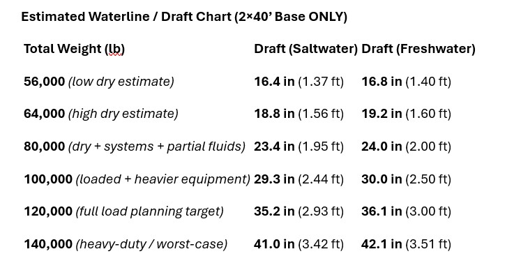
Estimated Waterline / Draft Chart (2×40’ Base ONLY)